- If this is your first visit, be sure to check out the FAQ by clicking the link above. You may have to register before you can post: click the register link above to proceed. To start viewing messages, select the forum that you want to visit from the selection below.

Announcement
How to check and adjust propeller shaft alignment.
- Latest Activity
- Time All Time Today Last Week Last Month
- Show All Discussions only Photos only Videos only Links only Polls only Events only

- Join Date: Aug 2010
- Posts: 1573
- Location: Long Beach, CA
- Boat: 2015 Z3, 1999 2100i
- Join Date: Feb 2016
- Posts: 3216
- Location: Boise, ID

- Join Date: Oct 2018
- Location: Parker, TX
- Boat: Tige R23
- Join Date: Aug 2016

- Join Date: Feb 2022
- Location: Windber, PA
- Boat: '06 24V
- MarketPlace
- Digital Archives
- Order A Copy
Prop shaft alignment
Nearly all marine engines are designed to be adjustable, to a point, relative to the propeller shaft by using adjustment or jacking nuts on their motor mounts. The adjustment should be thought of as no more than fine-tuning, the maximum range of vertical travel being limited to no more than an inch or two at the most, which is substantial when one considers that alignment is typically measured to just a few one-thousandths of an inch. Thus, the responsibility rests with the naval architect and boatbuilder to ensure that the design and execution of the engine installation guarantees near-perfect alignment with the shaft before the motor mounts are adjusted.
The other alignment There is another side to the alignment story; it involves the support and position of the propeller shaft relative to its bearings, the shaft log (the tube through which the shaft passes) and the engine. While engine alignment is, or is expected to be, well understood by most marine industry professionals, shaft alignment is, on the other hand, far more esoteric and well understood by far fewer in the industry. In my experience, precious few truly understand its importance and the consequences of misalignment, and fewer still understand the techniques and processes involved in making adjustments and corrections.
Contrary to popular belief, shaft misalignment rarely leads to vibration, as the bow or offset induced in a shaft by misaligned bearings is constant. Improper shaft alignment can lead to excessive shaft drag and a resultant increase in fuel consumption, as well as accelerated bearing and shaft wear.
| Shaft alignment can involve some esoteric measuring and alignment techniques. Make sure the boatyard crew working on your vessel is familiar with the process. |
A few years ago, I inspected a vessel while it was hauled out. When I came to the propeller, I made an unsuccessful attempt to rotate it in order to gauge the condition of the bearings and alignment. Regardless of how hard I tried, I was unable to rotate either shaft on this twin-screw 60-foot vessel. This is a clear indication of either severe shaft misalignment (as opposed to engine misalignment, which rarely imparts this sort of resistance) or, less commonly, swollen shaft bearings. While final alignment of an engine to its shaft should only be carried out once a vessel has been afloat for 24 hours, even when hauled out the shaft should turn without undue effort once adhesion between it and its bearings is broken.
How shaft bearings work In virtually all cases, propeller shafts are supported by one — and for longer shafts, sometimes as many as four — bearings, often referred to by their trade name, “cutless bearings.” Shaft bearings are pipe-like components, the outer shell of which is typically made of brass, or sometimes a fiberglass-like material (the latter is designed to be used on steel and aluminum vessels to avoid the corrosion potential caused by copper alloys), with an inner liner of grooved or fluted rubber. It comes as a surprise to many users that the sole source of lubrication and cooling is seawater; if water flow to the bearing is insufficient, or if it’s interrupted by marine growth or a line, net or other debris on the shaft, or if the shaft log water injection system is clogged, rapid bearing wear can ensue.
Shaft bearings may be found in and supported by struts — I- or V-shaped metal supports attached to the vessel’s hull, through which the shaft passes — and/or embedded within the shaft log in the keel or hull. When the vessel is built, the builder must make a concerted effort to ensure that bearings are properly located to support the shaft, while ensuring that they are also aligned with the theoretical shaft’s centerline, a line that is perpendicular with and begins at the center of the transmission output coupling, traveling aft through the bearings. The line must also be centered in and parallel with the bearings. If the builder is successful in ensuring this alignment, barring groundings or other damage, it should remain correct throughout the life of the vessel. While small adjustments may be made to the relationship between the engine and shaft by adjusting the location of the former, the shaft’s relationship to and alignment with the bearings should remain constant.
| Using epoxy set the position of a block on which a shaft bearing has been mounted. |
Analysis and adjustment In practice, it’s not uncommon to encounter shafts and bearings that are misaligned, and the greater the number of bearings, the greater the likelihood of misalignment. While shaft-to-bearing alignment can be challenging, aligning a shaft to several bearings, as well as the general location of the engine, can be daunting. As such, it’s easy to see how this process can go awry while the vessel is being built.
Traditionally, during construction or repairs, the process begins with a length of small-diameter yet stout string or wire, which is adhered to the center of the transmission output coupling. It is led aft through the shaft log toward the rudder, where it is anchored typically to a weighted object like a jack stand. Using this string or wire as a reference point, bearings (and, if present, struts) are positioned. When properly aligned, the bearings must remain centered on and parallel with the string or wire.
While this traditional approach is still used, more modern tools are now routinely employed; these include lasers and optical sights. Using a laser or sighting tool, an installer can position one or more bearings along the sight line with great accuracy. While this aspect of shaft alignment is critical, it’s the easy part. Setting the bearings in place permanently can be more challenging.
| Wedges are used to adjust the height and orientation to the shaft centerline. |
Initially, the strut or bearing is “dry fit.” That is, it’s positioned roughly to determine what needs to be done to align it with the shaft. The process typically involves a technique known as “casting.” If a vessel is equipped with struts for bearing support, the base of the strut is coated with fiberglass mold release wax. It is then set into a mixture of thickened reinforced epoxy and positioned so that it remains centered on and parallel with the string, laser or optical sight or shaft line. The strut is “hung” from support fasteners, and wedges are used to adjust its height and orientation to the shaft centerline. Once the position is set, the epoxy is allowed to cure, after which — thanks to the wax — the strut is easily removed. Wax is removed from the strut and the epoxy surface, and the strut is then set in bedding compound, ensuring a watertight seal with the hull. In some cases, the bearing centerline may be below that of the shaft. In this instance, depending on the degree of misalignment involved, a recess may have to be made in the hull to accept the strut’s base, the strut may require modification or a new strut may need to be manufactured altogether.
A similar process is employed for bearings that reside within a shaft log and strut. The bearing itself is waxed and set in epoxy, and wedges are used to position it so that it remains parallel with and centered on the shaft line until the epoxy cures. All bearings should be a light press fit in the shaft log or strut. Ultimately, bearings are retained using set screws; a minimum of two must be used, and they should be installed at 60 degrees to each side of the bottom centerline, or at the 4 o’clock and 8 o’clock positions (alternately, they may be installed at the 3 and 9 o’clock positions, but not above the horizontal shaft centerline). Set screws must be harder than and galvanically noble to the bearing shell; indentations (not holes), which the set screws engage, should be drilled into the bearing shell using a drill bit with a tip angle that matches that of the set screw. A thread-locking compound should be used on set screw threads.
|
A high-tech method for setting up proper alignment is to use an alignment laser. Using a laser, an installer can position one or more bearings with great accuracy. | |
Ultimately, once the shaft-to-bearing alignment is complete, even a long and large-diameter shaft should — with the benefit of nothing more than light lubrication from soapy water — rotate with relative ease using one hand.
Before entrusting your vessel to anyone for shaft alignment analysis or adjustment, carefully scrutinize their knowledge and experience on this all too important yet frequently misunderstood subject. Don’t lead; simply ask, “How do you ensure the shaft is properly aligned to the bearings?”
Steve D’Antonio is an ABYC-certified master technician and owns Steve D’Antonio Marine Consulting.

By Ocean Navigator
Marine Propeller Shafting and Shafting Alignment – Part 1
by Team TheNavalArch | Sep 20, 2020 | Marine Engineering , Maritime Industry | 3 comments

*****This article first appeared in July 2018 edition of Marine Engineers’ Review (MER), India. We’re reproducing it for the readers of our blog*****
Since 2013, Shaft Alignment Practice has undergone a change, with developments of Analysis tools. At the Shipbuilding stage, the Classification Society approves the OEM (Original Equipment Manufacturer) document for Shaft Alignment by verifying both the procedure and the actual running condition.
Subsequently, during regular drydocking surveys, the Classification society ascertains that the initial conditions are met. In case of any damage, the Class Society jointly with the Ship Repair Team carries out various inspections to ensure its conformance. One of the tests, the Jack Loads test, is also carried out to ascertain the condition of the Alignment if required. The graph of the Jack Load test when plotted allows an experienced technician to forecast or forewarn a possible worn out bearing which can be corroborated by Shaft oil lubrication condition monitoring and bearing temperature trends.
This article aims at explaining the theory and practice of propeller shafting work, as it is being undertaken by shipyards and ship repair facilities, and we hope this will give the operators superintendents at New Buildings and Dry Dock engineers a fairly good appreciation of the subject.
Introduction:
Propeller shafting installation and alignment are subjects often discussed in connection with both the building and repairing of ocean-going vessels. Despite the availability of a plethora of information on the subject in various platforms. we often hear questions such as,
– Should we re-sight the shaft line. when ships are being dry-docked for repairs?
– How shall we re-align the shaft after the same is withdrawn for surveys?
– What is the difference between ‘gap-sag’ alignment and alignment using angular and radial misalignment?
– Is it important to do an alignment in the middle of the night for accuracy (that is when the sun is down)?
In order to understand the answers let us look at the various common propulsion systems deployed in marine crafts.
Common Shafting Systems:
Directly Coupled Shafting: This is the most common shafting installation, which we find in cargo ships. Here slow-speed engines are directly coupled to the propeller shafting and mostly employ fixed pitch propellers. The typical installation is as given in the figure-1(a)

Figure 1(a) Slow speed engines with direct coupled to FPP
Shafting With Reduction Gear Box.
This installation is commonly found in classes of ships like workboats, naval/coastguard ships, dredgers, etc. These can be mainly two variants as shown in Figures 2(a) and 2(b). One is with a high-speed shafting between the engine and the gearbox, and the other without a high-speed shafting, the engines directly coupled to the gearbox.

Propulsion With Thrusters
In this case, the propulsion units are installed and coupled to the prime mover directly or indirectly, with long shafting. Alignment of these propulsion units with the prime movers does not follow the conventional shaft sighting and alignment procedure.

The Theory Of Shaft Alignment:
The success in alignment is in achieving near straight shaft line during operation conditions by following a sequence and practice during the hull erection process at the new building stage. Much of the preparation is carried out during the Design stage. The shaft-line is modeled along all possible conditions from Drydock to the Afloat stage for all probable Hull deflections. The behaviors of the shaft at the various conditions are verified for limits of deviation from the straight line. Investigations are also carried out to analyze the vibrations by an iterative process of Bearing relative offsets. Subsequently, the shaft bearing reactions, jack reactions in the closed condition of the static shaft, and open condition of the shaft over the bearings are generated. Then the gap-sag readings in the open-shaft condition are generated while in afloat condition and in drydock condition while due consideration is given for the hull deflections.
While carrying out the Iterative computations using Alignment software it is checked that the loads on bearings are commensurate with the bearing lubrication pressures designed by bearing OEM. It is also verified that no bearing is under-loaded or negatively loaded, while the alignment satisfies all Vessel representative conditions of loading. A typical computation can be seen in Figure 4 (a).

The principle of gap-sag and bearing reactions is based on the evaluation of shaft system on supports by continuous beam method. This approach Lies in resolving the statically indeterminate condition being simplified into a determinate condition by assuming an additional equilibrium process where the set slopes on either side of supports are equated.
Considerations of Hull deflections during the design stage: Using Continuous beam method with supports at Vessel. Jack points. (statically indeterminate structures), Hull deflections at the dry dock with respect to the final afloat condition can be computed. Principles can be seen in figures 4 (a) & 4 (b).
Figure 4.(c) afloat condition consideration of Vessel can be seen below.

Factors driving the New Trends and stringency:
New rules are now being drafted to introduce more stringent alignment methods. This is due to a spate of stern tube bearing wear down problems. This has come about due to various factors. The adoption of FEM methods in Hull structure design, for medium and Larger vessels to optimize on Hull scantlings, is leading to more flexible hulls. Again Finer HuLL forms are leading to Larger hull deflection from dry dock to the afloat condition and thereby more variation in the shaft line conditions. Many other factors such as the Movement of the HULL from Pre-fabrication Location to Drydock calls for re-establishing the shaft sighting and keelsighting.
Frequent stern tube bearing wear problems in pre-2013 alignments have made some OEM’s introduce stringent criteria in accepting Jack measurements.
Steps In Alignment During Building Stage:
Keel Sighting Stage:
The first step towards instaLlation of shafting and the propulsion system on any vessel is the vessel keelsighting
The first operation is keel sighting, and deciding on the keel line or baseline of the vessel, from which all measurements will be made. In a typical keel sight report of a vessel, it may be seen that the keel is not straight, but is within acceptable limits of requirement. The challenge is to decide on the optimum point from which the dimensions will be taken. The decision takes into consideration the concentricity of the shaft tine with the installed stern sections. the thickness of bolting down chocks for the main engine, gearbox and bearings on the shaft line, etc. Ideally. a chock thickness of 30 to 45 mm is preferred for a propulsion installation during the initial installation stage. This will ensure acceptable chock thickness post-launch, even after the vessel’s hull takes the final shape, and final alignment is carried out. ( Note: Chock thickness more than 7o mm and less than 12mm is not preferred for propulsion installation )
Here, there is a general question asked. Should we carry out the shafting work during day time or night time? We in India prefer these jobs to be done at night, as the hull deflects considerably during the day time because of the high ambient temperature prevalent in our country. The hull more or less settles down by around nighttime. Between 220o hrs and 07oo hrs, we get a reasonably steady state of the hull, free from extreme deflections. Hence, most of the line sighting is done during these time intervals.
Methods In Sighting The Shaft Line And Shafting Installation, Pre Launch:
The shaft line/lines can be sighted using multiple methods/instruments. The most commonly used methods are, Sighting using piano wires, optical instruments, or using the Laser.
Whatever is the method used for the final sighting of the shaft Line, initial shaft lines are established using the following methods:
Ship center Line, shaft center lines. critical frames marked on the dock floor
The above details transferred to the ship’s hull using plumbob/Laser plumbob
Height above lines established using water levels.
Once the off-center and height above baseline of the shaft lines are established, as mentioned above. the line/lines are established, either with a piano wire or optical sighting instrument or with a Laser sighting instrument. The propeller shaft bearing housings (stern bushes) can be installed either by press-fitting to machined bores in the stern structure or can be fixed to the stern structure by resin chocking.

In the case of a machined and press-fitted bearing installation, once shaft line is sighted and signed off between the yard, owner, and the class, bearing houses are machined using line boring equipment and finished to pre determined sizes. Care is taken to ensure that the ovally and taper in the finished bore is less than the interference that is recommended between the bore and the stern bushes. Once the bore is completed, stern bushes are machined to suit, with recommended interferences and press-fitted on to the bores.
In case of a resin chocked arrangement, the stern bearing bushes are aligned to the established shaft centerline, using the yard’s sighting procedure, and fixed in position with resin chocks. Once the bearings are fixed. Stern tube Lub oil piping and aft seal oil supply piping is completed, for oil-cooled installation.
For both oil-cooled and water-cooled installations, bearing temperature sensors are also installed at this stage.
Now the installation is ready for shafting insertion. Shafts are inserted from inboard or outboard, depending on the type of installation. For most of the conventional fixed pitch propellers. the shaft is inserted from inside the vessel. and for CPP propulsion the shaft is inserted from outside.
Once the shafts are in position, propeller is installed for a fixed-pitch propeller. The propeller is attached to the matching portion on the shaft and pushed up, as per the requirement of the propeller OEM.

After the fitment of the propeller/CPP propeller shaft, seals in the forward and aft are tightened for oil cooled installations. After this rope guards are fixed. The shaft installation is locked for protecting the same from slipping during launching/float out. The propeller shaft is pushed back by about 5-6mm (within the movement allowed by the seals) prior to locking of the shaft. This is to ensure enough gap between the shafts/engines/gearboxes for carrying out gap and sag alignment.
On completion of gap and sag alignment, and once the engine/gearbox is in position, this distance is pulled in to complete the installation,
Post Launch Alignment Activities: Final alignment of the shaft Line, the coupling of the various elements of shafting, final fixing of engines/gearboxes, pedestal bearings are carried out post launching of the vessel. This again depends on the experience of the shipyard and the data of previous vessels available to the yard. For example, many of the Japanese and Korean shipyards carry out most of the jobs that are done in the post-launch stage at the pre-launch stage itself, and post-launch only a verification of the job done is carried out for confirmation.
However, in Indian shipyards, most of the final alignment work is carried out post Launching of the vessel.

Condition Of Vessel For Post Launch Alignment:
In the case of larger cargo vessels, the alignment is usually carried out in the Launching draft of the vessel. However, for vessels with smaller size and Lesser draft, the ship is brought to even keel, with propeller immersion prior to carrying out final alignment. It is always desirable to keep the condition of the vessel unaltered during the course of alignment of the vessel, even though it may not be always practical.
That brings up to the end of Part 1 of this topic. In part 2, we’ll see the following
- Carrying out gap-sag alignment
- Evaluation of bearing reaction/load
Disclaimer: This post is not meant to be authoritative writing on the topic presented. thenavalarch bears no responsibility for the accuracy of this article, or for any incidents/losses arising due to the use of the information in this article in any operation. It is recommended to seek professional advice before executing any activity which draws on information mentioned in this post. All the figures, drawings, and pictures are property of thenavalarch except where indicated, and may not be copied or distributed without permission.
TheNavalArch Interview Series: Mr. Balakrishna Menon
by Team TheNavalArch | May 4, 2023 | Marine Surveys , Maritime Industry , Ship Design and Construction
Mr. Balakrishna MenonEngineering Director Mooreast (Asia) Pte Ltd TheNavalArch's Interview Series is an endeavor to get insights from the best engineering and business brains in the industry, and present them to its users for the larger...

Floating Rice Fields, the quest for solutions to combat drought floods and rising sea levels
by Team TheNavalArch | Apr 20, 2023 | Floating Wind , Loadouts , Ship Design and Construction
by Lim Soon Heng, BE, PE, FSSS, FIMarEST Founder President, Society of FLOATING SOLUTIONS (Singapore) Abstract Amazing as it seems, there is a case for growing rice on floating platforms in the sea. The capital expenditure to develop this is offset by the opportunity...

CAPSIZE OF LIFTBOAT IN TRANSIT
by Team TheNavalArch | Apr 12, 2023 | Maritime Industry , Ship Design and Construction , Ship Stability
This paper was originally presented in the 27th Offshore Symposium, February 22nd, 2022, Houston, Texas Texas Section of the Society of Naval Architects and Marine Engineers It has been reproduced here for the readers of TheNavalarch INTRODUCTION In 1989 a Class 105...

Designing a closed chock as per IACS rules
by Team TheNavalArch | Jun 26, 2022 | Marine Operations , Marine Transportation , Maritime Industry , Mooring , Mooring and Anchoring , Ship Structural Engineering , Towing
Introduction Chocks are used universally for mooring and towing operations on ships. For towing operations, Chocks are used for guiding the towing rope from the winch through the outer shell of the vessel to the tug. For mooring operations, the chock is used to...

The Optim22 method of hull optimization – Part 2
by Team TheNavalArch | Apr 1, 2022 | Maritime Industry , Oil & Gas , Ship Structural Engineering
This is a follow-up article to the previous article on Framed Structures Optimization. 1.1 Abstract A previous article introduced the Optim22 method. This one adds additional background information plus 3 more case studies to...

The Optim22 Method of Weight Optimization of Framed Steel Structures
by Team TheNavalArch | Mar 15, 2022 | Marine Transportation , Oil & Gas , Ship Structural Engineering , Uncategorized
1 Abstract A semi-automated structural weight optimization system is presented for framed structures of post and beam construction which is based on basic structural member design principles. The approach is to adjust member properties in a manner that...

Combating rising seas with floating structures
by Team TheNavalArch | Jan 30, 2022 | Floating Solutions , Maritime Industry , Naval Architecture
Introduction Rising sea level is an existential threat for many coastal cities. The sea is rising subtly but relentlessly at an exponential rate. Many predictions of how high and how fast it will rise in the next 50 years have proved to be understated. According to...

Sea Pressure Loads Calculation based on DNV Rules
by Team TheNavalArch | Dec 14, 2021 | Hydrodynamics and Resistance , Marine Transportation , Maritime Industry , Ship Design and Construction
Introduction Sea pressure loads are an important factor in the structural design of a vessel. What is sea pressure load? As the term suggests, it is the external pressure on the vessel due to the surrounding sea. What kind of pressure it is, and how to...

A quick empirical method for resistance estimation of planing vessels
by Team TheNavalArch | Oct 21, 2021 | Boating , Maritime Industry , Resistance and Propulsion
Resistance estimation for a vessel is a fundamental exercise in design of the vessel. Resistance is a property that depends on the vessel’s shape and form. A conventional ship-shaped vessel with a bulb will have completely different resistance characteristics compared...

Powering the maritime industry with Hydrogen – Part 2
by Team TheNavalArch | Oct 2, 2021 | Hydrogen , Maritime Industry , Naval Architecture , New technologies
Powering the shipping industry with hydrogen - Part 2: Hydrogen propulsion on a ship - opportunities and challenges Introduction In the Part 1 of this article, we explored the basic properties of Hydrogen as a fuel, and also the opportunities and challenges...

shaft targeting wiith electronic appliances


The online articles published by The Naval Arch Team are current, relevant and invaluable to the maritime operators of the present day. Thank You. Well Done!
Submit a Comment Cancel reply
Your email address will not be published. Required fields are marked *
Save my name, email, and website in this browser for the next time I comment.
- THE PRINCESS PASSPORT
- Email Newsletter
- Yacht Walkthroughs
- Destinations
- Electronics
- Boating Safety
- Ultimate Boating Giveaway
- Uncategorized
Shaft Alignment
- By Vincent Daniello
- Updated: September 15, 2009
ytgsep15yy525.jpg
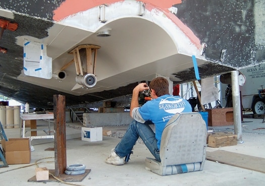
Advances in hulls, engines, propellers, and even acoustic materials have all made boats stronger, faster, and quieter. Today we’ve come to expect luxury-car comfort aboard 100,000-pound yachts traveling 30 knots. But the shafts, struts, and bearings that tie engines to props have changed little since the mid-1800s when the screw propeller eclipsed the paddle wheel, and quirks in this drive train often cause vibrations. Fortunately, a few specialists are employing sophisticated methods to find and eliminate vibrations from shaft and strut technology that far predate the Model T.
“Everyone wants their boat to run like a Lexus. They don’t want to feel a thing,” says Fred Zucker, president of Seaworthy Services in Palm Beach Gardens, Florida( www.oceanalloys.com ). “Unfortunately, the human body is particularly sensitive to the frequencies of vibrations typically found on yachts.” Zucker has been building yachts and chasing vibrations for over 35 years, back when a mechanic’s experience, intuition, and the soles of his feet helped track down annoying, repetitive thumps.
“We learned from trial and error what makes a boat shake,” Zucker says. “We’d take boats apart, fix something, put them back together, and go on a sea trial, but often we’d still get fooled.” Today Zucker relies on years of acquired knowledge, but uses sensitive accelerometers connected to computers to analyze the sources of onboard vibrations. “When something is thumping, we want to know how many times a minute-the vibration’s frequency-and how hard-its amplitude,” Zucker says. By determining the frequency, Zucker can match it to the offending equipment. A bent propeller, for instance, will vibrate at some multiple of shaft speed, depending on how many blades are damaged, whereas a bent propeller shaft taper is subtly different.
“You’ll see an abnormal propeller signature,” Zucker says, “But you’ll also get a thumping vibration at the frequency that the propeller shaft is turning.” Problems originating from an engine itself will usually show up at one half of engine rpm since, on four-stroke diesels, each cylinder fires on every other rotation of the engine. Misfiring generators, too, will vibrate at half their rpm, and other pumps and equipment can be tracked down similarly.
Zucker warns, though, that while measuring vibrations is an exact science, interpreting the results is still largely an art. “This is complex machinery moving in a dynamic environment,” he says. “You’ve got to understand the construction of the boat you’re working on as you’re taking these readings.”
Zucker says one common misdiagnosis is mistaking an exhaust issue-producing a vibration frequency that is some multiple of the number of cylinders times engine rpm-for a propeller problem-which vibrates at the rate the shaft is turning times the number of propeller blades. The close frequencies often compound either issue. “A vibration may start out as an exhaust problem at lower speeds and then become a propeller problem at higher speeds. Somewhere in between, if those two frequencies overlap, they may cause a much larger vibration than either the exhaust or the propeller would independently.”
Finding the cause, or causes, of vibrations is only half the battle. While many specialists employ equipment and techniques similar to Zucker’s, Seaworthy Services actually does the work necessary to mitigate the shakes. “There are some very smart people doing [vibration analysis],” Zucker says. “But we sea trial the boats and see the computer diagnosis, and then we take the nuts and bolts apart and actually see the problem, and either prove or disprove what the computer is saying.” Zucker enjoys the instant gratification, and he also learns nuances from each repair that aid him in future, tricky diagnoses.
As mentioned, misaligned propeller shaft bearings are responsible for many vibration issues. Zucker says about half of the boats he works on for vibration mitigation have at least one misaligned or misplaced strut or shaft log. The shaft log is the tube that allows the shaft to penetrate the hull, with the stuffing box or shaft seal at one end, and typically a bronze and rubber shaft bearing within. Fortunately, resolving these alignment issues has gone high-tech, too.
“The first step, and the key to getting it right, is to make sure the yard blocks the boat just like it sits in the water,” Zucker says. The age-old method relied on strings or wires suspended tightly across the boat, with measurements taken from these wires to key points. Today technicians use laser equipment developed for land surveying, which shoots beams of light at precisionadjustable horizontal and vertical angles. “We use multiple laser systems and set up numerous targets before the boat is hauled,” Zucker says. “Then we make sure we hit those targets again as the boat is blocked.” The goal is to prevent misshaping or twisting the hull by supporting it exactly as the water does. Engines, too, are targeted, so they remain in the precise position they’ll take when the boat is relaunched.
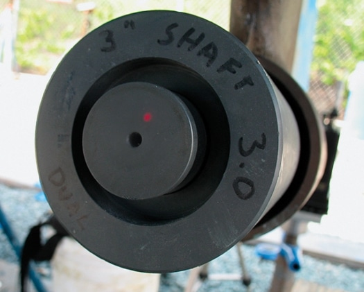
With the boat sitting on land just as it floats, and with the propeller shaft removed, Zucker shoots a laser from the propeller’s normal position, up through each strut and the shaft log, off a mirror placed on the transmission’s shaft coupling that bounces it back toward the propeller. “Each laser is set up on four-plane micrometers,” Zucker says. “We can adjust them up and down, side to side, or tilt them, measurable in thousandths of an inch.” Inserts in each strut ensure the laser finds both the strut’s center and angular alignment to within thousandths of an inch, and a target on the forward-facing surface of the insert indicates how far off center the reflected laser beam is. “When that laser beam shoots up to a mirror on the transmission’s coupling and straight back into itself, we know we’re dead-on,” Zucker says.
Rather than moving each strut, Zucker looks for at least two points that are aligned within tolerances, and moves other components to match, reducing the job cost. Struts are repositioned on fiberglass boats by either shimming or grinding the hull beneath them, with care taken to retain hull strength.
As the shaft bearings are aligned, the engine is also brought into precise alignment with the shaft. “Even experienced yacht people think that if you get the two faces of the propeller shaft coupling exactly parallel, the engine is aligned, but you’ve got a huge amount of weight, seven or eight feet of shaft and a heavy coupling, hanging out there unsupported once it leaves that last bearing,” Zucker warns. “All too frequently we find that the front end of the engine is about a quarter- to a half-inch low. The back is a bit low, too, because the engine had been aligned to a drooping shaft.” Zucker’s technicians prevent this with the same laser system, raising or lowering each of the four corners of an engine until the transmission’s output shaft is exactly parallel to and centered with the propeller shaft. A laser reflected off the coupling verifies the angle, and shooting it into a precisely centered target ensures vertical and horizontal alignment.
Zucker has further streamlined his system with high-resolution cameras viewing the laser targets and broadcasting to monitors in the engineroom and at the laser. “Rather than having one guy outside the boat telling someone inside the boat which way to move the engine, one or two guys working entirely within the engineroom can align an engine very quickly,” Zucker says. “When we slide the shaft up, we check that the coupling surfaces are parallel with a feeler gauge, but we’re usually within one or two thousandths. You can’t machine a shaft and coupling with the kind of accuracy we’re getting.”
Even with everything precisely aligned, some boats still vibrate. “Sometimes struts themselves will move. It’s a resonant frequency response to the shaft spinning through the strut. If you go a little faster or a little slower, it usually goes away, but a minor nick in a propeller blade may excite that strut and cause a noticeable vibration,” Zucker explains. “Like a tuning fork, there will be some frequency that every single-leg strut will vibrate at. Hopefully it is not at cruise rpm.” To avoid this, yacht designers try to design struts with resonant frequencies outside the normal range of propeller shaft rpms, though they’re not always successful.
Zucker and other vibration experts tell of innumerable variations and dozens of oddball circumstances that cause hard-to-find vibrations. In the past, yacht owners often just accepted them as too expensive or troublesome to find. But thanks to technology, today every boat can ride like a Lexus.
| ******Here are some additional resources for information on shaft alignment.** ******Sea Worthy Services** Palm Beach Gardens, FL Acton, MA Asbury Park, NJ (732) 922-8878 |
- More: Systems
- More Uncategorized

BoatUS Launches Online Advocacy Tool

Dock Danger

A Dream Fulfilled

3 America’s Cup Hashtags to Follow

Superyacht For Sale: Amels 180 “Galene”

Alia Yachts to Debut SAN Superyacht in Monaco
Top Bar Harbor Maine Sights For Visiting Cruisers

Always In Style: Ocean Alexander 85E For Sale
- Digital Edition
- Customer Service
- Privacy Policy
- Terms of Use
- Email Newsletters
- Cruising World
- Sailing World
- Salt Water Sportsman
- Sport Fishing
- Wakeboarding
‘Titanic’ Shipbuilder Harland & Wolff Files For Bankruptcy

China To Launch Its First Polar Expedition Cruise Line In 2025

World’s First Ship-To-Ship Ammonia Transfer Completed At Australia’s Port Dampier

Malaysia Launches Its First Hybrid Fast Crew Boat With Cutting-Edge Technology

How Sighting, Boring and Alignment of Ship’s Propeller Shaft Is Done?
It is seemingly easy to visualise a ship from the design drawings. And it is equally tough to turn the drawings into steel in a shipyard. That too, with the same precision as it was designed and drawn on paper, which brings us to one of the most relatable examples of this aspect.
The main engine of a ship is coupled to the propeller by means of a shaft. The translational motion of the pistons induces a rotatory motion on the crankshaft, which is in turn, coupled to the propulsion shaft. The shaft then passes through the stern tube. At the aft end of the shaft, and outside the stern tube, is coupled, the propeller . The arrangement is shown in Figure 1.

The centreline of the crankshaft must be along the centreline of the propulsion shaft, and the propeller. If that fails, the propeller will wobble about its position during running condition. Even few millimetres of wobbling can result in development of high stresses in the shafting arrangement, leading to structural failure. Not only that, the rupture of propulsion shaft can also lead to a major accident on ship.
As you can see above, it is very easy to visualize such an arrangement on paper or in a computerized drawing. But consider this. Suppose, during construction of the ship, the shaft was not positioned exactly along the crankshaft centreline. Given the fact that the shafts are long enough, up to more than 7 to 10 meters in average ships, the offset of the shaft centreline at the aft end would end up in order of centimetres. And that is not a design failure, but a failure in the production method.
So how do ship builders ensure the alignment of shafts exactly as per the design? In order to ensure that, builders follow a method called Boring and Sighting of the stern tube, which is described in the points below:
1. Sighting and Boring of a ship’s stern tube is done to establish practically the centreline of shafting, as accurately as per the design.
2. The stern tube consists of two bearings. One bearing at its forward end (called the forward bush bearing) and the other at its aft end (called the aft bush bearing). It is through the aperture of these bearings that the propulsion shaft passes. The clearings between the bearings and the shaft are very minute, and hence the shaft centre line is to be correctly established in line with the centres of the bearings. By maintaining this, it is ensured that the shaft centreline matches the centreline of the bearings, and the crankshaft. Again, the bearings are fitted within bosses (discussed in detail later). Follow Figure 2 to understand the arrangement of bosses in a stern tube.

3. The stern frame of the ship is the aft most structure of the hull and it is forged separately, and then attached to the remaining hull structure. The stern frame also houses the stern tube. The stern tube, in turn, houses the aft bearing. So the shipyard orders the manufacturer of the aft bush bearing with a machining allowance on the internal diameter. Why? Well, machining allowance means, if the required internal diameter of the bearing was 0.5 meter, the manufacture will order for an internal diameter with 0.49 meter. When the ship builder passes the shaft through the bearing, it is then, that he will machine the internal diameter to 0.5 meter, so as to match the design value.
4. Now, how do these bearings fit within the stern tube? The stern bearings are fitted within hollow steel cylinders within the stern tube, called bosses. Therefore, the shaft is housed within the bearings, which are housed within bosses, which again, are housed within the stern tube, as shown in Figure 2. So the aft boss houses the aft bearing and the forward boss houses the forward bearing. In order to be able to match the centreline of the bearing with the bosses with that of the bearings, the bosses are ordered with a machining allowance for their internal diameter (just for the same reason why the bearings have machining allowance in their internal diameter.)
5. The stern frame is welded to the hull structure and the stern bosses are welded to the stern tube.
6. Now arises a problem. Because of multiple welds on the hull structure and also because of the cutting allowances considered for each steel plate on the hull, the geometric centreline of the aft and forward bosses will not match the required centreline as specified in the design drawing.
7. A telescope is placed at the required height which matches the height of the design centreline. Multiple targets are placed at the aft and forward ends of the aft boss, forward and aft end of the forward boss, and along the centreline of the engine output flange.
8. The arrangement is then viewed through the telescope, and the position of the targets are aligned accordingly unless and until all the centrelines of all the targets appear to be in one line through the telescope.
9. The centres of the forward and aft boss are then marked. These centres should now match the centrelines of the forward and aft bush bearings respectively. So according to the obtained centres of the bosses, the internal diameter of the bush bearings are machined to the required internal diameter so as to be able to house the propulsion shaft. (This is why, the shipyard always orders the bearings with a machining allowance on the internal diameter.)
10. Care is taken regarding the achievement of correct internal diameter of the bush bearings (If the internal diameter is too large, the shaft will wobble within it, and the centrelines will not match. If the internal diameter is too less, it will not be able to house the shaft within the bearing) This is why, the internal diameter is measured precisely by a micro-meter after machining the internal diameter.
11. As a matter of fact, the forward and aft bush bearings are ordered with 5 mm machining allowance on their outside diameters. The outer diameter of these bearings are machined so that there will be an interference of about 0.01 to 0.02 mm between the internal diameter of the bosses and external diameter of the bearings.
12. This allows the bearings, to be pressed into the bosses of the stern tube, with an interference fit. Figure 3 shows the arrangement after the bearings are fitted within the bosses.

13. Once the centreline is achieved, the propulsion shaft is fed into the bearings, for installation.
Advanced technologies of boring and sighting also use laser technologies to ensure better precision than the above explained method. Boring and sighting is also used to line up the centreline of the rudder spindle with the steering gear equipment.
However, even though the shafting system is aligned such precisely during the building process in the shipyard, the shaft may still deflect from its original alignment due to the bending of the hull girder. Different bending scenarios occur, depending upon the loading conditions and the sea states the ship is sailing in. Therefore, the change in shaft alignment may occur due to bending of the propeller shaft, during this process.
Therefore, it is important for designers, to consider the effect of hogging and sagging of the hull girder on the change in alignment of the shafting system. To give a slight peek in the designing process of this aspect, let us understand that the underlying principle is yet very simple, and follows the Euler’s beam bending theory. In the design of the shaft for a ship, designers estimate the torsional, bending and shearing loads on the shaft, and thereby, the critical points of bending are found out. Accordingly, the position of the bush bearings (aft bearing and forward bearing) are decided so as to ensure that the deflection in the shaft is as low as possible in the worst loading conditions.
Classification societies, being related with the development of structural safety rules for ships on a proactive basis, have been involved in developing rules considering this effect. They have also researched various types of ship for this aspect, and documented the obtained statistics for future reference by ship designers, builders and dry dock personnel.
It is also very important and necessary to carry out regular checks for bearing clearances between the bush bearings and the propulsion shaft. Due to prolonged use in various loading conditions, the inner linings of the bearings tend to wear out, thereby increasing the clearances between the shaft and bearing metal. This may also lead to wobbling of the shaft.
During tests for checking the shaft alignment and deflection, the observations should be noted at lightship condition (in which case the shaft deflection will be minimum, and will exhibit the inherent deflection in the shaft), and in the fully loaded draft condition (wherein, the deflection will be maximum owing to the additional deflection due to the bending of the hull girder itself).
Disclaimer : The information contained in this website is for general information purposes only. While we endeavour to keep the information up to date and correct, we make no representations or warranties of any kind, express or implied, about the completeness, accuracy, reliability, suitability or availability with respect to the website or the information, products, services, or related graphics contained on the website for any purpose. Any reliance you place on such information is therefore strictly at your own risk.
In no event will we be liable for any loss or damage including without limitation, indirect or consequential loss or damage, or any loss or damage whatsoever arising from loss of data or profits arising out of, or in connection with, the use of this website.

Do you have info to share with us ? Suggest a correction

About Author
Soumya is pursuing Naval Architecture and Ocean Engineering at IMU, Visakhapatnam, India. Passionate about marine design, he believes in the importance of sharing maritime technical knowhow among industry personnel and students. He is also the Co-Founder and Editor-in-Chief of Learn Ship Design- A Student Initiative.
Read More Articles By This Author >
Daily Maritime News, Straight To Your Inbox
Sign Up To Get Daily Newsletters
Join over 60k+ people who read our daily newsletters
By subscribing, you agree to our Privacy Policy and may receive occasional deal communications; you can unsubscribe anytime.

BE THE FIRST TO COMMENT
can you please make an animation regarding about this please. would appreciate it. ! thanks!
This is a good rundown of some shipyard processes but there are even more advanced methods than dicussed. Most large ships are aligned using strain gauges and only use optical or lasers for very rough alignments. Find out.more at http://www.lamalotech.com
I want to join merchant navy
Hi plese send for me proseuder of main shaft alignment with laser in big ship best regard for you
Hi, thanks for the nice article. I have a small doubt. While aligning the shafts, what is the permissible gap and sag at the couplings? Or after the shafts are coupled, what is the permissible slope of the shaft at the coupling?
Leave a Reply
Your email address will not be published. Required fields are marked *
Subscribe to Marine Insight Daily Newsletter
" * " indicates required fields
Marine Engineering
Marine Engine Air Compressor Marine Boiler Oily Water Separator Marine Electrical Ship Generator Ship Stabilizer
Nautical Science
Mooring Bridge Watchkeeping Ship Manoeuvring Nautical Charts Anchoring Nautical Equipment Shipboard Guidelines
Explore
Free Maritime eBooks Premium Maritime eBooks Marine Safety Financial Planning Marine Careers Maritime Law Ship Dry Dock
Shipping News Maritime Reports Videos Maritime Piracy Offshore Safety Of Life At Sea (SOLAS) MARPOL
WAIT! Did You Download 13 FREE Maritime eBooks?
Sign-up and download instantly!
We respect your privacy and take protecting it very seriously. No spam!
- Vessel Selection Assist
- Pre- Purchase Guidance
- Building Your New Vessel
- Equipping Your New or Pre-Owned Vessel
- Boat Owner and Buyer Articles
- Sample Inspection Reports
- Testimonials
- Boat Buyers Gallery
- Captains’ Club
- Ready for Sea
- Refitting & Repairing Your Boat
- Vessel and Systems Inspection
- Boat Owners Gallery
- Industry Consulting
- Industry Articles
- Industry Gallery
- A Complete List of Photo Albums
- About Steve’s Photography
- Project Destinations
- Aircraft Flown
- Educational Videos
- About Steve
- Contact SDMC
- SDMC Lecture Offerings
- SDMC Webinar Lecture Series
- Seaworthy and Challenges
- Travelogues
- Feature Article
- Marine Systems Excellence eMagazine
The Ins and Outs of Engine and Shaft Alignment Part I

From the Masthead

The Ins and Outs of Engine and Shaft Alignment

A laser can be used to “sight through” a shaft. Here the laser has been positioned in the aft-most shaft bearing, and aimed at the transmission output coupling. When it’s centered, the shaft droop will have been eliminated. The pilot bushing is damaged, dents can be seen between the 12:00 and 2:00 o’clock position.
Engine and propeller shaft alignment are among the most critical aspects of propulsion system installation, reliability and maintenance. Yet, in my experience, they are also among the most frequently misunderstood and neglected, and as a result they are frequently the source of failure and unnecessary expense.
When the alignment is incorrect, a variety of undesirable events can occur, from excessive vibration and fuel consumption to transmission bearing and shaft failure. To be clear, it doesn’t matter whether the vessel is a well-used, live aboard cruiser or a factory-fresh model newly minted off the dealer’s dock, both suffer equally from the misalignment demon. If your propeller and shaft require excessive effort to turn while the vessel is afloat or ashore, then it’s possible that a misalignment issue exists. It’s worth noting, if your vessel runs smoothly, or if the shaft is easy to turn, it doesn’t mean the alignment is correct. Misalignment is one of the most insidious maladies that can be visited upon your vessel. Therefore, you should take no chances, make sure yours is correct. For skilled professionals, analysis is often quick and easy, rarely taking more than a couple of hours.

Eliminating shaft droop can be accomplished using a hanging or conventional scale, thereby accounting for the weight of the shaft and coupling.
Engine vs. Shaft
It’s important to make the distinction between the two different types of alignment that exist aboard virtually every vessel. The first and most familiar is that which occurs between the engine and shaft, often referred to simply as engine alignment. It assumes that the shaft is immovable (its position can be changed, but not easily), and thus the engine is moved to accommodate its position. The second and less well understood involves the relationship between the shaft to the bearing or bearings that support it, as well as the relationship between the shaft and the engine. Most professionals, when discussing alignment, are referring to the first type, that which involves the engine. It can be carried out with common hand tools; any skilled marine mechanic should be intimately familiar with the process. Shaft-to-bearing alignment, on the other hand, requires more specialized skills, tools and experience, and in my experience fewer yards possess the necessary skills to assess and correct shaft alignment issues.
Engine Alignment
For engine alignment, the primary area of concern is the interface between the transmission output coupling and the shaft coupling. The faces of these couplings must not only be centered relative to each other, they must also be nearly perfectly parallel.
Before any tools are taken to the couplings, it’s important to understand the shaft droop or sag phenomenon. Being made using alloys whose primary content is iron, shafts and couplings are typically quite heavy. Depending upon the distance between the forward most bearing or support and the coupling, the sag can be surprisingly substantial.
When I’ve discussed this issue with some mechanics they’ve expressed skepticism, ‘How could a two inch diameter steel shaft sag?’ they asked. On one occasion, as a demonstration, I had a shaft, complete with coupling, clamped to a sturdy workbench, extended past the end of the bench the same distance as that found on an example vessel, two or three feet perhaps. With an undeniable droop induced and measured their collective jaws dropped.

Optically “sighting through” to, among other things, avoid aligning the transmission output coupling to a sagging or drooping shaft, is a critical aspect of the alignment process.
Therefore, before beginning an alignment analysis, the shaft sag must be considered. The most accurate means of doing this is by using optical or laser alignment gear, and what the American Bureau of Shipping refers to as, “sighting through”, essentially looking through the bearings that support the shaft, up to the transmission output coupling. Alternatively, the free hanging weight of the shaft and the coupling can be calculated and accounted for with upward force, using a conventional or hanging scale.
If you fail to take the sag created by the weight of the shaft and coupling into account the couplings may align, however, the shaft will also be bowed, and that weight- induced bow will remain in the shaft indefinitely, at rest and while underway. Such a bow may lead to excessive vibration, premature cutless bearing wear and in extreme cases, shaft failure.
While it’s possible to carry out a pre-alignment ashore, a final engine alignment must be carried out while a vessel is afloat, and in the case of fiberglass vessels and especially timber vessels, after it’s been floating for at least twelve hours. Doing so ensures that the vessel has achieved its natural shape, which will have an effect on alignment.
Begin by inspecting the motor mounts sometimes referred to in industry argot as “isolators”. Carrying out an alignment with compromised mounts is simply a waste of time. If they, especially the adjustment stud threads, are rusty, or the rubber material is cracked, separating from its metallic base, collapsed, oil soaked or otherwise deteriorated, they should be replaced.

Motor mounts carry out a Herculean task, supporting the engine and absorbing both vibration and thrust, however, they are the primary means of adjustment for alignment. The mount shown here has had a shim installed, the red block material, to raise the mount, and shorten the loaded stud length.
Next, remove the coupling bolts and separate the two couplings. Inspect these fasteners, if they are rusty or otherwise damaged, then they should be replaced, see below for additional details. Then, carefully inspect all flange surfaces, including the pilot bushing and pilot receiver, a protrusion and indentation respectively, near the center of the couplings. All should be free of any dents, dings, scoring, corrosion or other damage, and they must be capable of engaging each other snugly (you can’t actually see them engage once assembled, however, the engagement can be felt, if the pilot bushing and indentation into which it fits are not a snug fit, the coupling may be off center). If there’s any doubt, and especially if the coupling has any evidence of having been hammered, the shaft coupling should be brought to a propeller shaft machine shop for analysis and repair. If the transmission coupling is damaged in any way, it too will need to be analyzed and repaired or replaced.
Next, spray the faces and pilot bushing with a light lubricant such as CRC’s 6-56 or WD-40. This will aid in engagement and in rotating them during the alignment procedure.

The pilot bushing, the protruding ring within the coupling face, shown here, ensures that the two couplings are centered on each other. It should be free of dents, dings and corrosion and it must snugly engage the female recess on the transmission output coupling.
Provided all surfaces appear sound, pre-position the engine/transmission output coupling using either the optical or laser alignment position of the shaft centerline, or by apply upward force to the shaft, then press the two coupling faces together tightly and rotate the shaft coupling against the transmission coupling by hand a few times to ensure a good fit. Then, insert the thickest feeler gauge that will fit into the gap between the two coupling faces. A maximum of approximately 0.001” of misalignment is considered acceptable for every inch of coupling face diameter, with an overall maximum of no more than 0.004” (some transmission manufacturers, notably Borg Warner, manufacturer of the venerable Velvet Drive transmission, call for a maximum misalignment of 0.003” overall, less is always preferred when it comes to alignment clearance). Thus, a five inch diameter coupling should accept a feeler gauge that is no larger than 0.004” (again, less is better) at any point around the interface. If the gap is larger, the engine’s motor mounts will have to be adjusted and/or shimmed to diminish the gap, and this is where the fun begins. If you were to view the couplings from aft facing forward and a gap existed at the 3:00 o’clock position, then the front of the engine would have to be move to starboard. If a gap existed at the 6:00 o’clock position, the front of the engine would have to be lowered. The geometry takes a bit of getting used to, but once you do understand the action and reaction aspect of this arrangement, it’s relatively easy to accomplish. Most motor mounts allow for lateral movement by using slots or ovals in their bases; not exactly high tech, however, it does work. Moving the engine from side to side can be a bit challenging, depending upon its size and weight, for larger engines a hydraulic jack may be required, while a simple lever, a 2×4 for instance, can be used for smaller engines. Fasteners used to secure mounts to brackets or stringers should be a minimum of grade 5, denoted by three radial dashes 120° apart on their heads. Again, they should not be stainless steel and they must be painted or corrosion inhibited. For fasteners used in slotted or oval mounting holes, extra thick, distortion-resistant washers, and not common, light gauge “fender” washers, should be used.

Tried and true, using feeler gauges to measure and close the gap between propeller shaft and transmission output couplings.
Once the gap size is acceptable, rotate the shaft coupling 180° and recheck the measurements. If any change occurs, the coupling, shaft or fit between the two is not true, in which case they will need to be removed and taken to a shaft shop for inspection, and a process known as ‘fitting and facing’, wherein the coupling, while fit to the shaft, is machined on a lathe to ensure its face is perpendicular with the shaft’s centerline. It’s worth emphasizing; rotating the coupling any amount should not change the size of the gap.
Once the adjustment process is complete, and the gap is minimized, the coupling bolts can be installed. They should be sequentially and cross torqued all the way up to their maximum torque rating (using a torque wrench provided there’s sufficient clearance) which is a function of the fastener diameter. Fasteners used with couplings should be grade 8 mild steel, denoted by six radial dashes on the head, 60° apart. Under no circumstances should stainless steel bolts be used. Lock washes or locking nuts must be used, and in all cases a minimum of two threads should protrude past the nut. Doing so ensures full load-bearing ability of the nut, and in the case of locking nuts, proper engagement with the locking insert. Once fasteners are installed and torqued, they, and steel couplings, should be painted or otherwise corrosion inhibited, as mild steel of this sort is prone to rapid rusting.
Ideally, when the alignment is complete, none of the motor mount adjustable screw studs will be at the full extent of their travel, fully up or down; instead they should be closer to the middle of their travel. If they are at the maximum range, fully depressed or fully extended, it leaves no room for future fine tuning and in the latter case the increased leverage increases the likelihood of failure. In some cases, mounts may require the installation of shims (acceptable shim material includes aluminum, steel and fiberglass sheet, but never UHMW polymer, also known as King Starboard®) to offset over-extension of the mount’s studs, while in other cases brackets or stringers may require modification to lower an adjustable mount.
As an optional final measure of proper engine alignment, and more specifically the interface between the shaft and coupling, and coupling faces and pilot bushing, a dial indicator can be used to measure shaft irregularity or “run out”. Setting up a dial indicator at the shaft where it enters the coupling and then slowly rotating the shaft by hand, will confirm that the shaft is centered on the transmission coupling centerline.
Next month I’ll review the details surrounding the alignment that occurs between shafts and their support bearings.
To read Part II, please follow this link .

You cannot copy content of this page
- BOAT OF THE YEAR
- Newsletters
- Sailboat Reviews
- Boating Safety
- Sails and Rigging
- Maintenance
- Sailing Totem
- Sailor & Galley
- Living Aboard
- Destinations
- Gear & Electronics
- Charter Resources
- Ultimate Boating Giveaway
Sailboat Propeller-Shaft Couplings
- By Steve D'Antonio
- Updated: June 19, 2019

If you’ve ever aligned your propeller shaft and engine, then you’ve handled the hardware that connects these two components together: the shaft coupling. While simple in form, couplings play a critical role in drivetrain reliability. If they are not properly installed, they can lead to vibration or worse — the separation of the shaft from the engine.
There are three primary types of couplings: straight, split and tapered, with the first two being the most common for smaller sailboat auxiliaries.
While straight-bore couplings are common, they lack the grip required for larger engines and props, which can place significant strain on the shaft-to-coupling interface. The challenge is getting the interference fit between shaft and coupling bore just right. If it’s too tight, driving the coupling onto the shaft may be very difficult, and if it gets stuck before it’s fully inserted, that can present a challenge. If it’s too loose, the shaft may begin to shift in the coupling with each forward-neutral-reverse shift evolution, which in turn will gall the key, allowing for more and more movement.
This scenario often ends with a sheared key and set screws, with the shaft and prop sliding out the shaft log, at which point they either screw their way into the ocean depths or strike — and jam — the rudder. If the shaft parts from the stuffing box altogether, a fire-hose-like geyser will erupt, after which the bilge pumps will be tested, and not in a good way. Installing a clamp ring on the shaft to prevent this scenario makes good sense as a safety backup. Better still, set up your shaft and coupling properly, and you’ll never have to test the clamp ring.

Split couplings are easily identified by their bifurcated design. While this coupling is really made up of one part, its aft end is divided into two sections that are clamped against the shaft using two or more machine screws. With this arrangement, the coupling can apply clamping action to the shaft. The split coupling offers one advantage over other coupling types, as it enables easy removal of the shaft by driving a pair of steel wedges or cold chisels into the gap between the two split halves.
Beyond this, there is no other benefit to using a split coupling, and I’d argue that rather than making it easy to remove, the primary mission of a coupling is to securely retain the shaft. Additionally, because it is split, and therefore moves or distorts each time a shaft is inserted or removed, the coupling face may not remain perpendicular to the shaft, which will affect the ability of the shaft to be aligned to the engine/transmission output coupling. In addition, it is possible to make a mistake during installation — for example, not torqueing pinch bolts in proper sequence, or pinching against a set screw — which leads to the coupler being off perpendicular, which can lead to a serious vibration. It’s worth reiterating, the only attribute of a split coupling is the ease of shaft removal.

Tapered couplings are popular on large horsepower applications and are the undisputed Cadillac of shaft-connection methods. Relying on the same principal used for the propeller-to-shaft interface, a cone-shaped hole in the coupling mates with a precisely machined cone-shaped male taper on the end of the prop shaft. Once the two are properly connected, and the retention nut tightened, they are very difficult to separate, which is exactly the goal. Separation, when intended, typically requires a puller — or a drift (a socket often works well) and longer coupling fasteners, which are used as jacking screws. Unlike the split coupling, a tapered shaft and coupling fit together the same way every time they’re assembled, so there’s no issue with retaining perpendicularity between the shaft and the coupling face, thereby ensuring proper alignment can be accomplished.
Next month, I’ll discuss coupling keys, keyways, pilot bushings, fastener and set screw selection, drift, roll, and taper pins.
Steve D’Antonio offers services for boat owners and buyers through Steve D’Antonio Marine Consulting .
- More: engine , Hands-On Sailor , How To , monthly maintenance , prop
- More How To

Surviving the Storm: A Sailor’s Tale of Hurricane Lee

Best Practices for Boat-Show Shopping

Grease the Wheels of Your Boat: A Guide to Proper Lubrication

A Bowsprit Reborn: A DIY Renovation Story

Savoring Superior: A Great Lakes Cruise To Remember

Point Your Compass Due South, Bitter End Yacht Club Reopens October 23rd.

Pre-Owned: 1988 Hylas 47
- Digital Edition
- Customer Service
- Privacy Policy
- Terms of Use
- Email Newsletters
- Cruising World
- Sailing World
- Salt Water Sportsman
- Sport Fishing
- Wakeboarding
- ◀ Back to Menu
- Laser Microgage PRO Plus
- Laser Microgage 2D
- Laser Microgage 2000
- Pro-Line Laser Kit
- Pinpoint Capture™ Software
- Alignment Applications
- Alignment Mounts
- Alignment Components
- Custom Alignment Equipment
- Accessories
- Straightness & Linear Measurement
- Squareness & Perpendicularity Measurement
- Spindle Alignment
- Parallelism Measurement
- Flatness & Planar Measurement
- Machine Leveling
- Runout Measurement
- Bore Alignment
- Shaft Alignment
- Precision Angular Alignment
- Building Materials
- Electronics
- Machine Tooling
- Manufacturing
- Shipbuilding
- Video Tutorials
Whitepapers
- ROI Calculator
- Alignment Tips
- Application Discussion
- Free Alignment Report
Case Studies
Terminology
- Receive Info
- Pinpoint Advantage
- Testimonials
- Pinpoint In The Press
- Our Management Team
- Capabilities & Technology
- Made in America
- Careers at Pinpoint Laser Systems
- Request a Quote
Free Report
Propeller Shaft Alignment with Microgage 2D Laser
Introduction.
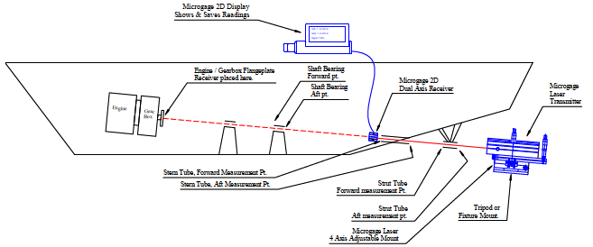
The alignment of propeller shafts on ships, tugboats, large pleasure yachts, and other vessels can be a time consuming and difficult task. In some cases, this alignment may be done from the engine or gearbox moving aft through bearing supports, through the stern tube, and then through a strut tube or cutlass bearing to the propeller. Commonly, the stern tube will already be in place and the shaft alignment is referenced off of this fixed tube or perhaps the stern tube and an exterior strut tube. The Laser Microgage can adapt to each of these approaches and with a little bit of practice the alignment is made very precisely and quickly.
The following application note describes this alignment process and the equipment that you will need. If you have questions about this process or ideas to share, please contact our Pinpoint engineering team at 800-757-5383.
Items Needed
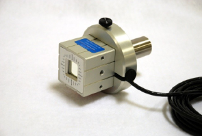
- Microgage 2D Alignment System
- 4 Axis Laser Mount
- Alignment Tripod
- Microgage Bore Mount
- Receiver Extension Cable
- Plastic Targets for Rough Alignment
- Tape Measure
- Notepad for results
Optional Items:
- Microgage 4D Receiver
- Laser Support Stand
Propeller Shaft Alignment – Forward Alignment Approach
This alignment technique uses a laser mounted in the region of the propeller and projects a laser reference beam forward. This laser reference beam passes through the strut tube or cutlass bearing, the stern tube, support bearings, if any, and to the engine or reduction gearbox.
When the laser beam is in place, centered, and aligned it can then be used for checking the placement and alignment of each part of the propulsion system.
Typically, the stern tube or perhaps the strut tube is fixed in place and the alignment of the propeller shaft is based on the orientation of one or both of these components. The angle of propeller shaft and its random orientation in space (depending on the location of the boat) means that the alignment of the laser beam will probably not be level to gravity or tied to convenient mechanical surfaces and features in the area. The objective for rough alignment is to get the laser beam as close to centerline and parallel with the shaft axis for either the strut tube or the stern tube.
Aligning the laser beam along the center of the shaft line involves a rough alignment followed by a fine alignment. The rough alignment is work done by eye to get the laser into a general parallel and centerline location. There are two methods you can use for this; we call them the “mirror approach” and the “peep-hole”.
- The Mirror Approach involves having a short section of propeller shaft or a plug with a mirror on the end of it. The mirror should be marked on its surface at a point that is nearly centered on the shaft or plug center – a sharpie marker and a small dot do the job nicely. Place the shaft section or the plug in the bore tube and aim the laser at the centering mark on the mirror. Adjust the laser position until the laser beam hits the mark on the mirror and reflects back to the beam port on the laser itself. Now, if you turn the shaft section or the plug in place you will notice that the laser beam will trace a circle near the front of the laser. This is normal. You can now adjust the laser position until the reflected laser beam both hits the mirror mark and swings symmetrically around the laser port on the laser housing. Once achieved, you should be very close to optimal laser alignment.
- The Peep-Hole approach uses two plugs with holes centered in each. This technique is improved by having the plug nearest to the laser fitted with a round window and a simple mark or scribe in the center. The laser beam is adjusted until the beam passes through the mark on the nearest plug and hits the hole or reference point on the most distant target plug.

Once the laser beam is roughly aligned you should be ready for fine alignment. Before we talk about this there are some suggestions about plugs and fixtures that might be helpful.
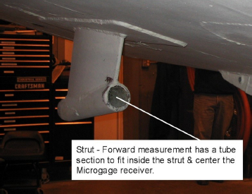
With the laser positioned below and behind the transom, the reference beam is aimed forward and up as it passes through the strut and then on to the through hull and finally on to the engine mount area. An ideal fixture for the holding the Microgage receiver at the aft end of the strut is a shaft section perhaps 4 to 6 inches in length with a flange on it to connect to the back side of the Microgage receiver. The Microgage 2D standard receiver is housed in a 2-inch cube and the zero-point is in the center of the optical port, 1 inch up from the base and 1 inch in from each edge. A number of customers have found it useful to mount the receiver on a plate with a ridge or step that the base and one edge can rest against to define the location of the receiver. The threaded mounting holes on the receiver are 10-32 and having these holes slightly oversized allows you to move the receiver to the side and base reference edges. This way, you can position the receiver so the zero-point is on the centerline of your shaft section. If the receiver is not perfectly centered this is OK, by rotating the fixture and averaging the readings you can remove any fixture errors – more on this in a bit.
This same type of fixture can also be used for the measurements at the aft end of the through hull. Another successful approach we have seen is to make a small adapter plate that secures to the back side of the Microgage receiver and then in turn secures to various shaft sections, mounts, etc.
Our recommendation is a tube that is perhaps 3 to 6 inches in length for solid mounting and removal.
We have designed plug fixtures for customers and the two photographs above show these fixtures designed for a 1-inch and 2 ¼-inch precision bore. This fixture can be used with the fixture behind the receiver or in front of the receiver in cases where the laser is coming through the center of a bore tube.
For larger propeller shaft diameters, such as those found on large commercial ships and military vessels, Pinpoint has developed several types of expanding receiver mounts. By changing the length of the three support arms this design can accommodate several different tube sizes. With these suggestions on mounting fixtures, the best measurements are made when you can actually rotate the receiver mount in the strut tube or the stern tube. In this way you can take a pair of measurement readings and average out any fixture errors or fit problems that may be present. This is advantageous because you can ease the tolerance (and the cost) for the mounting fixtures, and as the fixtures wear with use you can still keep using them. Perhaps most important, the insertion and removal of the fixtures is easier when there is a little spacing gap to keep the fixture from becoming wedged in the bore tube.
The final alignment process begins by placing the receiver and its mount into the aft end of the stern tube (or the strut tube if you are using that) and turning the receiver until the label is facing upwards. The Microgage display will provide you with a reading for the vertical orientation and also the horizontal orientation of the laser beam, relative to the center of the receiver and the tube. Record these readings and then turn the receiver and its mount by a ½ turn in the tube and record the readings again. Averaging the two vertical values and the two horizontal values will tell you how far the laser beam is from the exact center of the tube. Note these averaged values and move the receiver and its mount to the forward end of the bore tube. Repeat the process noting the Microgage readings when the receiver label is up and then down and finally average these values.
Final alignment of the laser beam to the center of the bore tube is accomplished when these averaged values are the same for the forward and the aft end of the bore tube. The 4-Axis Mount can be adjusted and the readings repeated until the averaged values at the forward and aft end of the tube are nearly the same. We recommend adjusting one axis at a time – perhaps vertical first, followed by horizontal. Adjusting the laser beam so that it is on the centerline and parallel with a tube section involves some trial and error adjustments. We find that applying a little math to the process can often speed up these adjustments as well. It is important is to think about the measuring accuracy that you need for your particular project and find a point that is acceptable. The Microgage 2D system can be aligned to better than 0.001 inch of a bore centerline and parallel to its edges, but in many instances this may involve unnecessary time and effort if the required alignment tolerances are less demanding.
We begin by aligning the laser beam so it is nearly parallel to the bore or tube section that you are using as a datum and then make adjustments to bring the beam onto the centerline. It is important to work on the angular alignment of the beam first, because the angular adjustments are large and increase as you move away from the laser. Centerline errors are constant and more manageable to work with.
If further angular adjustment is needed, you can calculate a target number to adjust the laser too. This is done by measuring the length of the datum tube between the front and back measurements and determining the ratio of this distance to the distance between the front of the laser and the front of the tube. If for example the ratio of these distances is 5:1 and the difference between the vertical laser readings is 0.010 from the front to back end of the tube, you will need to adjust the laser 0.050 inch as measured on the front position in order to correct the angular difference of the laser to the tube length. This may move the beam further away from the centerline, but aligning the angular error should be done first. You can repeat this process for the horizontal axis (X axis) as well. Now you have a beam that is parallel to the datum tube although probably off the centerline.
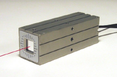
Now that you have the laser beam aligned parallel to the tube wall, there are three choices to proceed forward;
- Adjust the beam to the centerline,
- leave the beam where it is and use math to compensate for its centerline position, or
- disregard the centerline beam offset, because it may be well within your tolerance errors.
We will discuss these in reverse order. If your tolerances are such that the present position of the laser beam to the centerline is adequate, your alignment of the laser is done. We do recommend writing the readings down and checking the laser periodically to make sure it has not moved during your alignment.
Once you have eliminated an angular beam error you are left with a constant centerline error. This centerline error will remain constant along the laser beam path and can be either adjusted out or compensated for. You can compensate for a constant centerline error in your measurements by simply remembering to remove it from each reading. For example, if your laser beam is parallel to the bore tube but below the centerline by 0.025 inch and to the right of centerline by 0.035 inch your target readings for aligning to the centerline of the bore tube would be – 0.025 inch and -0.035 inch. If you are comfortable working with offsets and adding or subtracting them from your readings this method can save you a lot of time. Furthermore, the Microgage 2D Display has a feature where you can add offsets to your readings so in the example above you can enter +0.025 inch as a vertical offset and -0.035 inch as a horizontal offset and the display will read 0 and 0 when the laser is aligned with the center of the datum bore tube and other bearings and bore tubes along the path of the propeller shaft.
Some customers chose to bring the laser onto the centerline so that the laser is both parallel to the bore and on the centerline simultaneously. The 4-Axis Mount has four adjustments, two that control the angular orientation of the laser beam and two that control its linear position. In the case of our earlier example, the vertical lift control would be adjusted to bring the laser beam up (Y or vertical axis) by 0.025 inch. The lateral adjustment is used to move the laser beam to the left by 0.035 inch so that the laser is on the centerline. Whenever these lateral adjustments are made, you should recheck the measurements at the front and rear of the datum tube to make sure that the angular alignment is still OK. Typically the angular alignment is done, linear adjustments are made to bring the beam back to centerline, and one more minor pair of angular adjustments are made. This approach ensures that the laser is both parallel and on the centerline of the datum tube. We always recommend that the measurement readings be written down and periodically checked to make sure that the laser has not been accidentally moved.
Now, your laser reference beam is aligned to the selected bore tube (either the strut tube or the stern tube) and you are ready to proceed with the rest of your alignment. If you are aligning the strut tube or cutlass bearing, the receiver is placed at the aft end of this tube, with the receiver label facing upwards and the readings on the display noted. The receiver can then be turned, in place, ½ turn and the readings noted again. Averaging the vertical and the horizontal values will give you the exact position for the aft end of the tube relative to the centerline of the laser reference beam. (Again, you may feel that your alignment tolerances are OK without turning the receiver fixture and averaging for each position.). Repeat this process for the forward end of the bore tube and your measurement values will tell you if the placement and orientation of the tube is correct.
Now the laser reference beam can be used for checking and adjusting the location of shaft support bearings inside the vessel. The bearings provide a good rotational mount and the receiver can be fitted into the bearings and readings taken to position the bearing assembly to its correct up/down and left/right position.
Finally, the laser reference beam is used to align the engine or a reduction gearbox. The receiver is attached to the center of the propeller shaft take-off flange on the engine or gearbox and a reading taken with the receiver label in the up position. These readings should be noted. The take-off flange is then turned ½ turn until the receiver label is facing downwards and the measurement values recorded. Once again, the up/down and the left/right values should be averaged. The averaged values provide the distance and the direction that the engine or gearbox must be moved (left/right, as well as up/down) in order to bring it onto the centerline of the propeller shaft. The process requires a bit of practice but becomes routine very quickly. We recommend keeping a notebook so that measurements can be recorded and reviewed as each alignment step is made.
The Microgage 4D Receiver can provide excellent measuring and alignment results if used on support bearings and particularly for the alignment of the engine or a reduction gear. The ability of the 4D receiver to display, simultaneously, the linear position and the angular orientation of an engine or the gearbox makes the alignment process easier and faster. Watching the linear values provides information on shims and linear adjustment and the angular data helps improve the parallelism alignment of the engine to the drive shaft.
Propeller Shaft Alignment – Aft Facing Alignment Approach
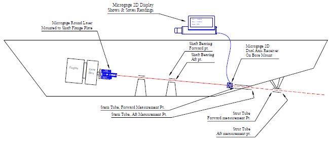
Application Notes
- Roll & Web Alignment
- Aligning Spindles, Chucks
- Reciprocating Ram Alignment
- Run-Out Measuring
- Long Measuring Runs
- Propeller Shaft Alignment
- Updated Propeller Shaft Alignment
Talk to our alignment specialists
Talk to our alignment specialists.
[formidable id=16]
News & Information from the Trusted Laser Alignment Experts

Pinpoint Open House, Nov 9th
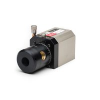
Check out all of our 90-Line family.
Learn More About Capture Straightness Routines
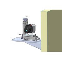
Custom solutions to fit your exact alignment specifications.

Sign up to receive alignment tips, product updates & more.
Do You Have Questions?
Log in or Sign up
You are using an out of date browser. It may not display this or other websites correctly. You should upgrade or use an alternative browser .
How to align this prop shaft
Discussion in ' Inboards ' started by holdfast , Mar 17, 2014 .
holdfast Junior Member
Hello, I have to align the propeller shafts on this boat. It is a little bit more complicated than usual as each shaft has four supporting points. There are two bushins outside the hull (as you can see in the picture), the shaft gland, a ball bearing and another thrust bearing before the Aquadrive system. I don't really know wich of the supporting poins is in the right position yet. I'm planning to do it with a laser, any advice please is allways helpfull. Cheers.
michael pierzga Senior Member
The first strut..p bracket ....will be trouble. How is it mounted in the hull ? Is it adjustable, shims, set into chockfast or epoxy Are there three cutlass bearings ? I believe the rule for distance between shaft bearings is 30 times diameter. Your shaft looks long and thin.
gonzo Senior Member
The struts were there already, so unless the hull had some structural damage, they should be OK. The engine should be aligned in the water after the hull swelled up. Planked boats get loose when dry and change shape. The fastener pattern shows it is either double planked or seam battened which minimized the problem.
Possible that wood boats change shape. Be careful that the aft jackstand its not deforming the hull. Have a carefull look when you pull the shaft.
Thanks Michael anf Gonzo for your replies. I attach some pics of the seal, the ball bearing and the thrust bearing. We are going to change the seal and the ball bearing and of course the bushings from the struts. The whole shaft needs to be aligned from 0 as it is not perfectly centered. I have installed new engines and there is no way to aligned them up with the engine mounts adjusting margin. Now the engine mounts are all the way to one side and they are still not aligned. My concern is if the struts need to be adjusted, it is going to be very difficult as the haven't been taken apart for ages. Are you sure the boat changes the shape after less than one month out of the water or with the jackstands? I know is made of wood but it is pretty solid too! I was planing to do all the job in the shed and I think there is no other choice except leaving the enging alignment after the launching... I think the starting point is to put the engines in the center position of the mounts, try to align the shaft betweeen there and the aft strut, wich I will have to check if it's in the right position too (I don't know how yet..) I will keep you updated, any advise allways help Cheers. [/IMG]
PAR Yacht Designer/Builder
This is a pretty critical aspect of a new engine install, so if you're having difficultly with the associated problem solving necessary in these type of upgrades, you'd be best advised to hire someone that has a few dozen installs under their belt to help. Basically, you just can get it close, while on the hard and you fine tune to a few thousands of an inch, once she's taken up. Anything less than this will insure issues, once underway.
Hard to see what your engine installation looks like. It would be much easier to move the engine into the shaft run , rather than reseat all the struts and bearing and bring the shaft to the new engine position. Chances are that your p bracket setup is reasonably well aligned Saddle bearings are easy to shim and adjust. If some misalignment is found in your P bracket Setup it may be easiest to adjust the saddle.
- Advertisement:
CDK retired engineer
The shaft alignment is simple and can be done without special equipment. Once the shaft is removed and new cutlass bearings in place you could use a laser to check the alignment, but when you push the shaft back in, you certainly feel if one of the bearings is off center. The engine is a different matter, because even with a laser you can only align in one plane and there may still be an axial angle.
Dialing in an alignment on a v-drive
Single engine, dual independent props for cat?
Advice on how to convert inboard jet drive boat to propeller....
Inboard Prop Shaft Thrust Bearing/Mount & Hydraulic Get Home
initial vibration of inboard prop when put in fwd or rev
Prop thro transom
Here's one i have not heard...how close should my prop be to my rudder.
Help with stern tube/propshaft design
New prop shaft coupling with new shaft
Propulsion for passagemaker
- No, create an account now.
- Yes, my password is:
- Forgot your password?

Visit our Popular Forums
- Monohull Sailboats
- Multihull Sailboats
- Powered Boats
- General Sailing
- Antares Yachts
- Fountaine Pajot
- Lagoon Catamarans
Cruising Business
- Boat Classifieds
- General Classifieds
- Crew Positions
- Commercial Posts
- Vendor Spotlight
Life Aboard a Boat
- Provisioning: Food & Drink
- Families, Kids, & Pets Afloat
- Recreation, Entertainment, & Fun
- Boat Ownership & Making a Living
- Liveaboard's Forum
Seamanship, Navigation & Boat Handling
- Seamanship & Boat Handling
- Training, Licensing, & Certification
- Health, Safety, & Related Gear
- Rules of the Road, Regulations, & Red Tape
Engineering & Systems
- Const. / Maint. / Refit
- Product / Service Reviews
- Electronics: Comms / AV
- Electrical: Batts / Gen / Solar
- Lithium Power Systems
- Engines & Propulsion
- Propellers & Drive Systems
- Plumbing / Fixtures
- Deck Hdw: Rigging / Sails
- Aux. Equipment & Dinghy
- Anchoring & Mooring
Photo Categories
- Member Galleries
- Life Onboard
- Sailing in the Wind
- Power Boats
- Cruising Destinations
- Maint. & Boat Building
- Marine Life
- Scuba Diving & Divers
- General Photos
Recent Photos

Listing Categories
- African Cats
- view more »
- Crew Wanted
- Crew Available
- Enhance Your Account
- Meet the Mods
- Meet the Advisors
- Signup for The Daily Cruiser Email

| ||||||||||||||||||||||||||||||||||||||||||||||||||||||||||||||||||||||||||||||||||||||||||||||||||||||||||||||||||||||||||||||||||||||||||||||||||||||||||||||||||||||||||||||||||||||


COMMENTS
The alignment you will be checking is the space between the propeller shaft coupler and the output coupler from either the transmission or the v-drive. 1) Locate and identify the propeller shaft coupler. On inboards, it's easy to see at the end of the transmission and on a wakeboat, has 4 bolts connecting it to the propeller shaft coupler.
Learn how to ensure proper alignment of propeller shafts and bearings on your vessel, and why it matters for fuel efficiency and bearing life. The web page explains the techniques and tools used for shaft alignment, and the consequences of misalignment.
Learn how to align a prop shaft with an inboard engine by taking the wobble out of the shaft and adjusting the engine mounts. Follow the step-by-step instructions and check the gap between the coupling halves with a feeler gauge.
So doing a propeller shaft alignment, or at least check is the best answer. This is normally done using feeler gauges in between the faces of your drive coupling faces. This has some limitations but is much better than a lot of others that dont check theirs.
Definitely better in water where boat/engine operate. Should actually be floating for 24 hours or longer before aligning, so Boat can take it's floating shape based on keel hanging rather than boat sitting on it and impact of rigging load. Number of hours seems a bit high - but not outrageous.
Learn about the theory and practice of propeller shafting installation and alignment for different types of marine propulsion systems. The article covers the design, analysis, and verification of shaft line, bearing reactions, and jack loads for new building and repair stages.
Best part is now the prop shaft goes through the middle of the hole in the hull and the log gland without forcing, lines up perfectly with the gearbox flange and I can turn the prop with my pinky, instead of needing 2-3 fingers. Just need to check the motor alignment and job done, but that is a daylight job. Couple of pics to show what I did.
Propeller Shaft Couplings. Split Hub Propeller Shaft Coupling Kit (ZF 63/68 A/IV, Velvet Drive) Split Hub Propeller Shaft Coupling Kit (ZF 220 A/V/IV) Split Hub Propeller Shaft Coupling Kit (ZF 800 80 85 A/IV, ZF 220PL, 280A/IV, 286A/IV, 301, MG506 5061 507) Split Hub Propeller Shaft Coupling Kit (MG 509) All ZF Marine Parts
WOULD LIKE TO GET ON BOARD BRUPEG?If you want to see all of Brupeg's episodes and behind the scenes bonus content, help make the channel & boat great plus ph...
As the shaft bearings are aligned, the engine is also brought into precise alignment with the shaft. "Even experienced yacht people think that if you get the two faces of the propeller shaft coupling exactly parallel, the engine is aligned, but you've got a huge amount of weight, seven or eight feet of shaft and a heavy coupling, hanging out there unsupported once it leaves that last ...
Engine should be equally supported on all four mounts.Tighten all motor mounts, recheck alignment with feeler gauges and bolt coupling halves together. Lastly, in neutral, rotate shaft by hand. It should spin freely without any binding or rubbing on the stern tube. Job requires patience.
1. Sighting and Boring of a ship's stern tube is done to establish practically the centreline of shafting, as accurately as per the design. 2. The stern tube consists of two bearings. One bearing at its forward end (called the forward bush bearing) and the other at its aft end (called the aft bush bearing).
The maximum tolerance for shaft wear is just one thousandth of an inch. The shaft shown here has been condemned as a result of excessive wear, caused by gross misalignment. In last month's column I reviewed the importance of, and techniques for, ensuring proper engine alignment. That is, the alignment between the engine and the propeller shaft.
When it's centered, the shaft droop will have been eliminated. The pilot bushing is damaged, dents can be seen between the 12:00 and 2:00 o'clock position. Engine and propeller shaft alignment are among the most critical aspects of propulsion system installation, reliability and maintenance.
Alignment wise is definitely better, meaning the gap difference between flange face is lesser. However, I do note that when the prop shaft is free from the gear coupling flange it droop down. There is about 1" of verticle play. When do the alignment, I just let the shaft droop down and set the engine mount height accordingly. Is this correct?
Updated: June 19, 2019. The shaft of this straight coupling has been knurled to improve the interface between the two. The wire in the set screw should be neater and tighter. Steve D'Antonio. If you've ever aligned your propeller shaft and engine, then you've handled the hardware that connects these two components together: the shaft ...
The objective for rough alignment is to get the laser beam as close to centerline and parallel with the shaft axis for either the strut tube or the stern tube. The Microgage Laser needs to be positioned at the aft end of the vessel and the laser beam directed along the center of the shaft run going forward. The laser transmitter is mounted onto ...
CDK retired engineer. The shaft alignment is simple and can be done without special equipment. Once the shaft is removed and new cutlass bearings in place you could use a laser to check the alignment, but when you push the shaft back in, you certainly feel if one of the bearings is off center. The engine is a different matter, because even with ...
Boat: IP445. Posts: 35. Re: Alignment of propeller shaft to engine. The proper way to align a shaft is not a feeler gauge. Mount a dial indicator to one shaft and set the clock on the other, with no bolts. Rotate one shaft 360. Then put the bolts in and rotate 360 again.
A discussion thread about how to align the prop shaft, strut, log and skeg on a sailboat. Users share their experiences and advice on whether to do it on the hard or in the water, and how to deal with possible changes and adjustments.
Re: Aligning motor, couplings, propeller shaft. I would use stainless steel shafts and not brass, much harder, and less likely to bend. brass shafts in brass stuffing tubes is also a very bad idea. friction will cause the brass to swell, both the shaft and the tube, swelling will lead to the two parts seizing.
Apr 5, 2023. #3. Aligning a prop shaft is a very tedious process and it is seldom explained well. As you have noted, it is possible to get seemingly correct feeler gauge values at the motor coupling faces even while the shaft is not correctly aligned with the stern tube. You mentioned that you hit a log.